![]()
Ultimate Guide: Eliminating Edge Cracks in Automotive PCB Assembly for Zero-Defect Manufacturing
If you are managing an SMT production line for automotive electronics—whether you’re building Engine Control Units (ECUs), EV Battery Management Systems (BMS), or Advanced Driver Assistance Systems (ADAS)—you know the stakes. A field failure in consumer electronics is just a warranty claim; a field failure in an automotive sensor at 70 mph is a catastrophic recall.
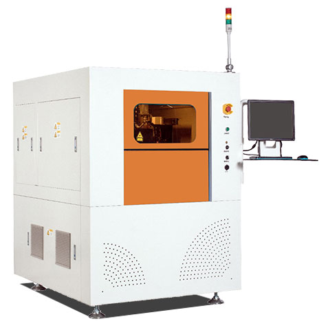
Here is the direct answer to your yield rate problems: To entirely eliminate edge cracks, protect sensitive surface-mount components, and easily comply with strict IATF 16949 quality standards, you must transition your final panel separation process to a pcb laser cutting machine.
Why do we strongly recommend this upgrade? Because traditional mechanical separation methods apply bending stress to the fiberglass substrate, fracturing fragile ceramic capacitors located near the board edge. A UV laser uses a non-contact cold ablation process. The immediate benefit is absolute zero mechanical strain on the board, a microscopic kerf width, and burr-free edges that won’t contaminate sealed automotive housings.
In this guide, we are sharing our direct factory-floor experience to explain exactly why edge cracking happens, how to optimize your production process, and the real-world data you need to justify upgrading your equipment.
1. The High Stakes: Why Edge Cracks Destroy Automotive PCBs
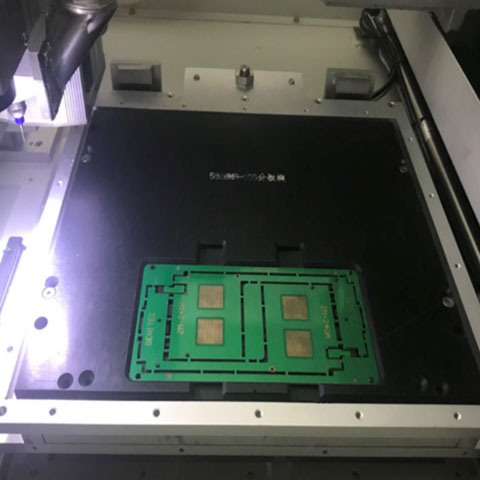
When we audit automotive SMT lines, the most painful issue we see is perfectly assembled, high-value panels getting destroyed in the very last step: depaneling. Your engineering team spends weeks perfecting the solder paste inspection (SPI) and thermal reflow profiles, only to introduce latent, invisible defects during board separation.
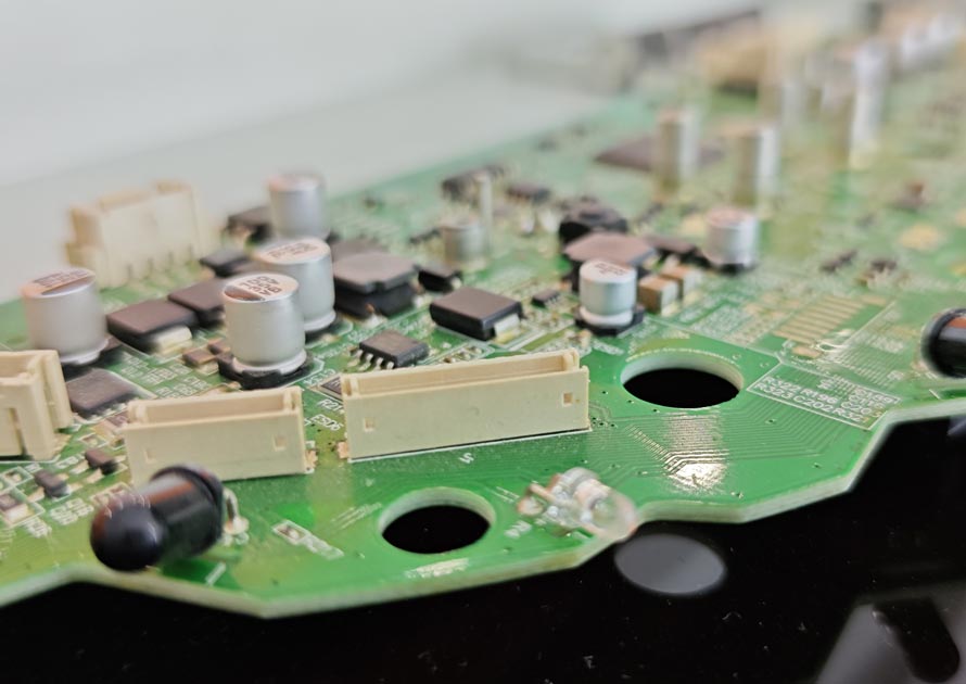
The root cause is always mechanical stress. Modern automotive printed circuit boards (PCBs) are densely packed to save space and weight. It is incredibly common to see Multilayer Ceramic Capacitors (MLCCs) and Ball Grid Arrays (BGAs) placed within 1.0mm of the routing tab or V-score line.
Ceramic capacitors are incredibly brittle. If the FR-4 board flexes even a fraction of a millimeter during separation, that bending strain transfers directly into the rigid solder joint, causing a micro-crack inside the component’s internal ceramic layers. These micro-cracks are a nightmare because they often pass end-of-line electrical testing. The vehicle ships, and months later, constant engine vibration and thermal cycling cause the crack to expand, leading to a dead short.
The Industry Data: According to engineering tests on mechanical stress during board separation, traditional hand-breaking or using a rolling blade wedges the material and generates severe stress peaks perpendicular to the cut. This is a primary driver of component failure.
2. Why Traditional Depaneling Fails (And Why Laser is the Upgrade)
We constantly get asked by factory owners: “Can’t we just use our old equipment?” Let’s break down how traditional methods compare to modern laser technology based on real-world automotive applications.
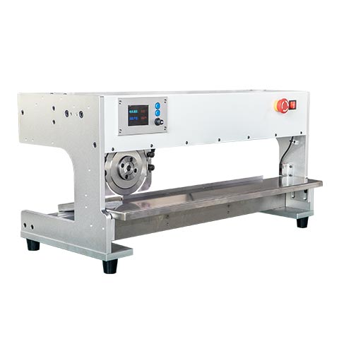
- The Problem with Saws: A v groove cutting machine system is excellent for cheap consumer goods because it is fast. However, it uses a rolling wedge blade to force the fiberglass apart. This generates massive localized stress. You must keep components far away from the cut line, which wastes valuable board space.
- The Problem with Punching: A punching machine uses a custom die to stamp out boards instantly. The violent impact shock makes it highly unsuitable for high-reliability automotive boards; the shockwave can shatter MLCCs instantly.
- The Limitation of Routers: A standard pcb router machine is currently the industry workhorse. It mills away the material and generates far less stress than saws or punches. However, it still uses a physical bit that vibrates. As the bit dulls, the vibration increases, pushing the mechanical strain closer to the danger zone for sensitive components.
The Ultimate Solution: This is why top-tier automotive EMS providers are moving to a pcb laser cutting machine.
Instead of grinding or wedging, a 355nm UV laser vaporizes the FR-4 and copper layer by layer. Because no physical tool ever touches the board, there is zero bending strain and zero vibration. Furthermore, it leaves no fiberglass dust or burrs, ensuring technical cleanliness—a hard requirement for IATF 16949 supplier qualification.
3. Best Practices: 3 Steps to Achieve Zero-Defect Depaneling
Buying the machine is only the first step. To truly eliminate edge cracks and optimize your automotive assembly line, you need to implement optimal processes. Here are three best practices we deploy when setting up a new line.
Practice 1: Design for Depaneling (DFM Clearances)
How to Start: The reliability of your board is determined during the CAD layout phase. You must establish strict keep-out zones near the cut lines.
The Solution: If you are using a mechanical router, industry standards require a minimum clearance of 0.3mm to 0.5mm from the routed edge for standard components, and up to 1.5mm for stress-sensitive MLCCs.
The Laser Advantage: By upgrading to a laser depaneling machine, the laser’s microscopic 25μm kerf width allows you to safely place components much closer to the edge. This enables engineers to shrink the overall size of the ECU or pack more functionality into the same footprint without risking micro-cracks.
Practice 2: Optimize Processing Parameters for Material Types
How to Start: Operators often use the same cutting parameters for every batch. This leads to poor edge quality and thermal issues.
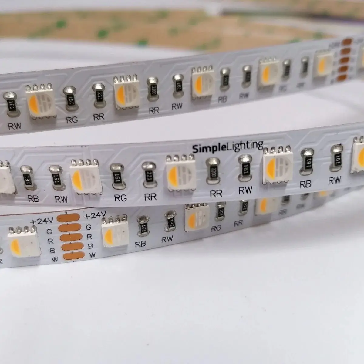
The Solution: You must match your machine parameters to the material. For example, if you are forced to use physical routing on standard 1.6mm FR-4, the ideal parameter window is generally a spindle speed of 40,000–60,000 RPM paired with a feed rate of 50–100 mm/s. However, if you are cutting flexible polyimide circuits (FPC) for automotive displays, routing will tear the material. You must switch to a UV laser and utilize short-pulse technology to prevent heat from melting the thin polyimide films.
Practice 3: Implement Smart Automation
How to Start: The safest, stress-free cut in the world doesn’t matter if an operator bends the board with their hands while pulling it out of the machine.
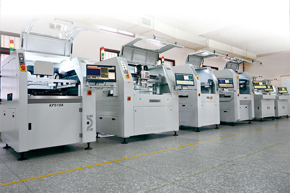
The Solution: Integrate your laser system directly into your SMT line using inline depaneling automation. Use automated vision alignment (CCD cameras) to guarantee precise cuts. Use robotic unloaders to pick up the separated automotive boards and place them straight into ESD-safe trays. Removing manual human handling removes human error.
4. Data Breakdown: Mechanical Strain Comparison
To put the importance of your equipment choice into perspective, look at the typical strain generated by different methods. Keeping the micro-strain (με) as low as possible is the absolute key to preventing MLCC cracking.
| Depaneling Method | Typical Strain (με) | Component Risk Level | Recommended Application |
| UV Laser Ablation | < 50 με | Very Low (Safest) | Automotive ECUs, Rigid-Flex, Micro-medical |
| CNC Router Milling | 50 – 150 με | Low | Standard Dense FR-4 Boards |
| V-Groove Saw | 200 – 400 με | Moderate | Simple grid arrays, consumer goods |
| Manual / Punching | > 500 με | High (Dangerous) | Low-end electronics, prototypes |
Data aggregated from independent PCB stress testing reports.
5. The ROI: Why the CapEx is Justified
We hear this from Factory Owners constantly: “A high-end UV laser system costs more than a standard router. How do I justify this?”
Here is how we break it down for our clients. While the initial capital expenditure for a laser is higher, the Total Cost of Ownership (TCO) is actually lower for high-reliability automotive applications:
- Zero Consumables: You never have to buy, stock, or replace expensive carbide router bits again.
- Zero Rework and Scrap: When an ADAS sensor board fails an electrical test due to a router-induced microcrack, you lose the board, the expensive chips, and the labor. Laser cutting brings the defect rate related to depaneling down to virtually zero.
- Winning Tier-1 Contracts: Having a stress-free singulation process physically in your factory allows you to bid on strict automotive contracts that explicitly forbid mechanical routing due to cleanliness and vibration concerns.
Frequently Asked Questions (FAQ)
Q1: How close can I safely place a ceramic capacitor to the cut path?
A: If using a mechanical router, we recommend keeping MLCCs at least 1.0mm to 1.5mm away from the edge to be safe. If you upgrade to a UV laser cutting machine, because there is zero mechanical vibration, you can safely place components fractions of a millimeter away from the cut line without risk of cracking.
Q2: Does the heat from the laser damage the PCB material?
A: No. When optimized correctly using UV short-pulse technology, the thermal impact (Heat-Affected Zone) is minimal and strictly controlled—often under 10 micrometers. It vaporizes the material so quickly that the surrounding board structure does not have time to absorb damaging heat.
Q3: Are these systems suitable for separating metal-core PCBs (MCPCBs) used in automotive LED headlights?
A: Processing Aluminum-backed boards (often rated 94V-0) requires specific methods. While high-power lasers can cut thin metals, for thick aluminum bases, specialized routing with 2-flute coated bits and reduced feed rates is often required to prevent edge cracking on the metal base.
Q4: Can we use a mechanical router for high-density Flexible Printed Circuits (FPC)?
A: We strongly advise against it. Flexible polyimide circuits lack the rigidity to withstand the rotational force of a milling bit, leading to tearing, chatter, and delamination. For any FPC work in automotive displays, a laser system is the only reliable choice.
Q5: How does a laser system improve our IATF 16949 compliance?
A: IATF 16949 requires strict control over manufacturing consistency and contamination. Mechanical methods create fiberglass dust and leave burrs that can detach inside a sealed automotive module. Laser depaneling leaves a chemically clean, burr-free edge, completely eliminating the risk of particulate contamination in your final assembly.