
How to Choose PCB Routing Tools to Improve Cutting Quality and Extend Tool Life
Jadual Kandungan
The short answer
Choose PCB routing tools by matching tool diameter, flute geometry, cutting direction, coating or substrate, and usable flute length to the PCB material and route. Then validate the tool with the real spindle, feed rate, fixture, dust extraction, and edge-quality target. The “best” router bit is the one that produces stable good boards at the lowest total cost per cut.
A tool catalog cannot see your copper distribution, glass weave, aluminum core, tab design, board support, component clearance, or production volume. That is why copying another factory’s tool and speed often gives disappointing results.
Why this matters in PCB depaneling
Routing happens after much of the PCBA value has already been added. A process problem can damage a finished assembly, interrupt downstream flow, or create a latent quality concern. That is why we evaluate the complete cutting system: the pcb router machine, spindle, tool, board support, program, dust extraction, inspection, and maintenance practice.
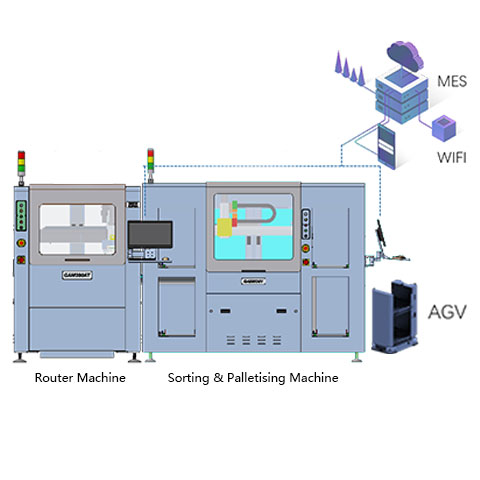
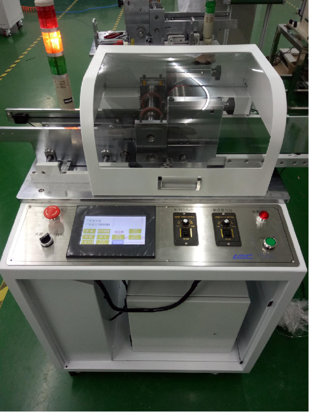
SEPRAYS router specifications show how these elements work together. The GAM 386 bottom-cut PCB router, for example, lists adjustable spindle speed, automatic tool changing, router-bit detection options, CCD teaching, and a dedicated dust collector. The GAM 360AT in-line PCB separator adds automated loading and unloading for line production. Specifications help narrow the choice, but sample qualification proves the process.
Key factors and their production effect
| Factor | What it controls | Risk when ignored |
|---|---|---|
| Tool diameter | Kerf, stiffness, corner radius, breakage resistance | Choose the largest diameter that fits the geometry |
| Flute geometry | Chip formation, cutting force, edge finish | Match the substrate and cut direction |
| Flute length | Reach and bending | Use only the length needed for the panel |
| Rotation/cut direction | Board pull, burr location, fixture load | Validate with support and component side |
| Material/coating | Wear resistance and heat behavior | Compare cost per accepted route, not unit price |
Start with a measured baseline
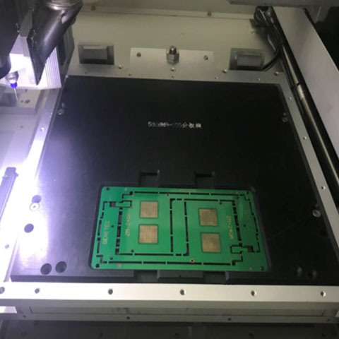
Create a controlled tool trial. Hold the panel, spindle, extraction, and program constant. Compare candidate tools over enough routing length to see wear, not just first-piece finish. Measure edge quality, dimensions, burrs, dust, noise, tool breakage, and router-bit consumption.
Collect at least the following before making a change:
- PCB material, thickness, copper structure, panel dimensions, and route length.
- Current tool, spindle speed, feed rate, depth, cut direction, and fixture method.
- Edge-quality defects, dimensional results, tool consumption, alarms, and rejected boards.
- Dust-cleaning frequency, filter condition, air pressure, and extraction observations.
- Cycle time including loading, tool changes, cleaning, inspection, and unloading.
- Machine model, serial number, software revision, and approved spare-part numbers.
Use a controlled test instead of guesswork
Change one important variable at a time whenever practical. Keep the same panel lot and inspection method. Run enough material to expose wear and heat, then compare accepted boards rather than first-piece appearance alone. Photograph edges, record route length, and save the recipe with the result.
A small-diameter bit may reach tight corners, yet its lower stiffness can increase deflection and breakage on thick FR-4. A larger tool may last longer but cannot follow the required radius. The right answer may be a design change, two-tool strategy, or different depaneling method.
When a result changes, stop and identify whether the source is material, tool, machine, support, extraction, program, or handling. Random parameter adjustment may hide the cause and make the next shift harder to control.
Build the solution around the real failure mode
Spindle and cutting tools
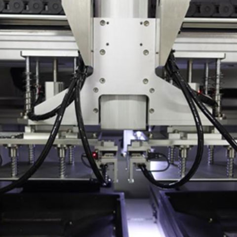
Runout, clamping, balance, temperature, speed stability, and bearing condition directly affect the tool path. Haas maintenance guidance, while written for machining centers, illustrates the engineering principle: spindle taper and test-bar runout should be measured and tool interfaces kept clean. Use the limits and method supplied for your PCB router rather than copying another machine’s tolerance.
Dust extraction
Donaldson describes a dust collector as a system of source capture, ducting, fan, filters, and containment. The same system view matters in PCB routing. A powerful collector cannot compensate for a leaking hose, damaged brush, blocked filter, poor hood position, or open enclosure. Review appropriate PCB depaneling accessories with the machine configuration.
Board support and handling
Fixtures, grippers, conveyors, and vacuum support must hold the panel without bending sensitive areas. Confirm component height, edge clearance, panel stiffness, and unload orientation. For delicate or flexible products where mechanical contact is the dominant risk, compare a laser depaneling machine rather than forcing a routing process.
Maintenance and control plan
- Define the normal operating window and approved recipe.
- List daily, weekly, usage-based, and supplier service tasks.
- Assign each task to an operator, technician, engineer, or supplier.
- Set measurable acceptance limits rather than “check condition.”
- Prepare tools, approved parts, safety steps, and forms before the maintenance window.
- Record findings, measurements, parts replaced, and follow-up actions.
- Review repeat failures and adjust the interval using evidence.
- Back up programs and verify recovery before software or controller work.
How to evaluate ROI
An inexpensive bit that needs frequent changes may cost more through downtime and quality checks. Calculate tool cost per accepted board, including change time, rejected panels, spindle load, and extraction cleaning.
The basic formula is simple: annual verified benefit minus annual operating cost, compared with the purchase and integration cost. The hard part is using honest inputs. Measure good boards per scheduled hour, not theoretical machine speed. Include scrap, rework, tool changes, filter service, technician time, spare inventory, and restart qualification.
Review the full range of PCB depaneling machines and automatic equipment when the problem extends beyond one component. Sometimes the best ROI comes from a spindle or vacuum upgrade. Sometimes the current machine architecture is the constraint.
Supplier and acceptance checklist
- Can the supplier test real production panels and document the result?
- Which parameters, parts, and maintenance steps are machine-specific?
- What are the expected wear items and normal lead times?
- How are tool life, runout, extraction, and accuracy checked?
- Which tasks can factory technicians complete without affecting warranty?
- What training, remote support, and field service are available?
- Which measurements define final acceptance?
- How will recipes, backups, revisions, and spare compatibility be controlled?
Common mistakes to avoid
- Choosing by purchase price without calculating cost per accepted board.
- Changing several process variables at once and losing the root cause.
- Using generic parts without checking compatibility and revision.
- Waiting for visible defects before inspecting wear or contamination.
- Ignoring extraction because the machine still completes the route.
- Keeping no record of tool life, alarms, maintenance, or replacement parts.
- Using a short demo to claim long-term reliability.
A practical troubleshooting sequence
When routing quality or machine performance changes, protect the product first. Stop the affected lot, identify the last known good board, and keep suspect boards separated. Do not immediately raise spindle speed or reduce feed. Those changes may hide the symptom while increasing heat or tool load.
- Confirm the correct product, panel revision, program, tool, and fixture are loaded.
- Inspect the tool for wear, breakage, contamination, insertion depth, and slip.
- Check the collet, spindle interface, runout condition, temperature, noise, and air supply.
- Inspect panel support, clamps, grippers, vacuum fixtures, and route clearance.
- Check the capture brush, hood, hoses, filter, collector bin, and visible dust pattern.
- Compare the current parameters and machine data with the approved baseline.
- Run a controlled first-piece test and document the result before releasing production.
This order moves from simple identification errors to tool, machine, support, extraction, and program causes. It also gives the next shift a clear record. If the symptom remains, contact the equipment or spindle supplier with measurements, photos, alarms, sample information, and recent maintenance history.
Quality checks that connect maintenance to the board
Maintenance is useful only when it protects product requirements. Pair machine checks with board-level evidence. Depending on the PCBA, the control plan may include edge burrs, fiber pullout, dimensions, tab remnants, surface contamination, component condition, and visual inspection around sensitive parts.
For a new tool, spindle, fixture, vacuum setup, or repair, inspect more than one board. Check output after the machine reaches normal temperature and after enough route length to expose early wear. Where product risk justifies it, engineering may add strain measurement, functional tests, cross-section analysis, or customer-specific reliability checks.
Keep the result with the recipe and maintenance record. That creates a useful chain of evidence: what changed, who approved it, which panels were tested, what passed, and when the process returned to production.
KPIs for continuous improvement
| KPI | What it reveals | How to use it |
|---|---|---|
| Accepted boards per scheduled hour | The total effect of cutting, handling, cleaning, alarms, and changeovers | Compare before and after changes |
| Tool cost per accepted board | Whether tool life improvements create real value | Include change time and rejects |
| Unplanned downtime by cause | Which subsystem creates the largest production loss | Prioritize maintenance and spares |
| Interventions per shift | How often operators must correct the process | Target recurring reasons |
| First-pass yield after depaneling | The board-level outcome of the complete process | Separate routing from upstream defects |
| Maintenance compliance | Whether planned tasks occur on time | Review overdue critical work |
Review trends, not isolated good days. A lower tool cost is not an improvement if burrs or interventions increase. Faster cycles are not useful if extraction falls behind. The target is stable output of accepted boards at a controlled total cost.
How to roll out a change safely
Use a staged release. Begin with an engineering trial, then a limited production lot, followed by a monitored ramp. Define who can approve each stage and what evidence is required. Train all affected shifts before the new setting, part, or maintenance interval becomes standard.
For spare parts and accessories, confirm labeling, storage, shelf conditions, machine compatibility, and installation instructions. For software or recipes, save a verified backup and rollback point. For extraction changes, review airflow, disposal, filter access, and relevant safety requirements. For spindle or cutting changes, verify runout, warm-up, tool clamping, edge quality, and dimensions.
After release, schedule an early review. The first week of normal production often reveals handling details that a controlled trial misses. Close those actions before declaring the improvement complete.
FAQ
What router-bit diameter is best for PCB depaneling?
Use the largest diameter that fits the route geometry, component clearance, machine collet, and required corner radius, then validate it on samples.
Why do PCB router bits break early?
Common causes include excessive runout, too much engagement, poor support, incorrect feed or speed, recutting dust, wrong insertion depth, and damaged collets.
Can one bit cut FR-4 and aluminum PCB equally well?
The materials load tools differently. Use supplier guidance and separate validation rather than assuming one recipe suits both.
When should router bits be replaced?
Replace them at a validated wear limit based on route length, edge quality, dimensions, load, or monitoring data, before quality drifts.