![]()
PCB Laser Depaneling for Rigid-Flex Boards: No Stress, No Delamination
When we walk onto the factory floor of a high-reliability electronics manufacturer—whether they are building advanced wearable medical devices, foldable smartphones, or critical aerospace avionics—we frequently encounter the exact same engineering nightmare. You have spent immense capital designing high-density rigid-flex printed circuit boards (PCBs), only to watch them delaminate, peel, or fail right at the very last step of the SMT production line: the singulation process.
Here is the direct answer to your yield rate problems: If you are currently using physical, contact-based cutting tools to separate rigid-flex panels, you are actively inducing mechanical shear force that destroys the board’s internal adhesive bonds. To entirely eliminate mechanical stress, prevent polyimide tearing, and achieve true zero-defect manufacturing, you must transition your production line to a pcb laser cutting machine utilizing 355nm UV technology.
Why do we strongly recommend this upgrade for your factory? Because a high-performance UV laser relies on a 100% non-contact process known as “cold ablation.” The immediate, measurable benefits include absolute zero mechanical vibration, no substrate warping, the complete elimination of fiberglass burrs, and a microscopic 25μm kerf width that allows you to maximize your panel yield and save massive amounts of money on expensive rigid-flex laminates.
In this comprehensive guide, we are sharing our direct engineering experience from the factory floor to explain exactly why rigid-flex boards delaminate, how to optimize your laser singulation process, and the real-world data you need to justify upgrading your depaneling equipment.
1. The Hidden Danger: Why Mechanical Depaneling Destroys Rigid-Flex PCBs
To truly understand why the laser solution works, we first need to break down the specific failure mechanisms that occur during traditional board separation.
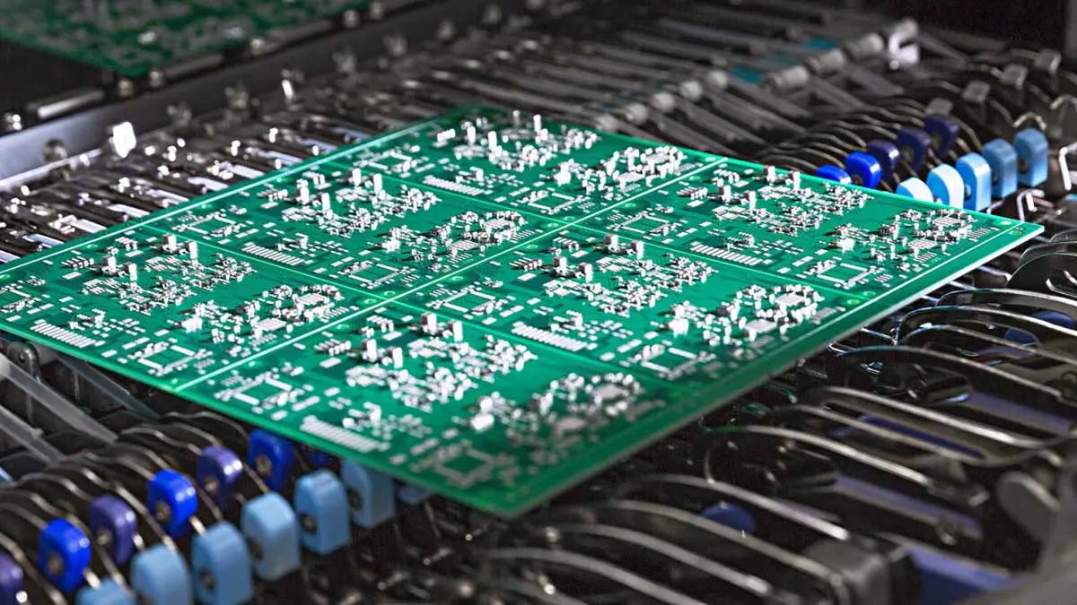
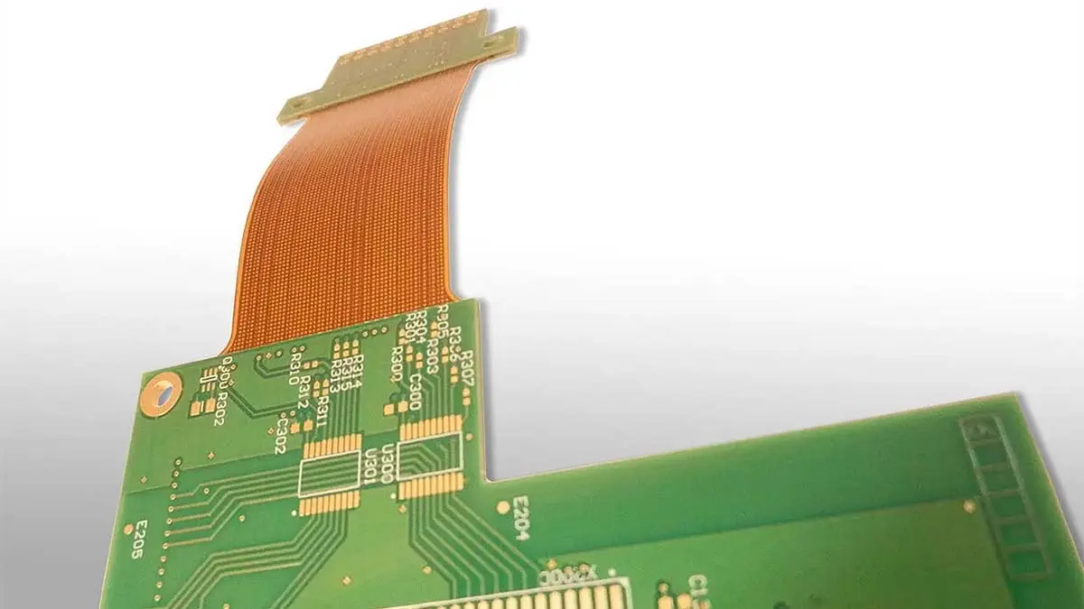
Rigid-flex PCBs are incredibly complex structures. They are hybrid materials created by pressing together flexible polyimide (PI) films, acrylic or epoxy-based adhesive layers, and rigid FR-4 glass-reinforced epoxy. These distinct materials have vastly different physical properties, tensile strengths, and coefficients of thermal expansion.
When you attempt to cut this delicate hybrid material using a traditional pcb router machine, the high-speed spinning solid carbide bit does not slice the material cleanly. Instead, the micro-flutes of the router bit physically grab the soft, flexible polyimide layer and attempt to drag it away from the rigid FR-4 core. This localized, violent shear stress rips the adhesive bond holding the layers together.
This failure is known as delamination. Once delamination begins at the microscopic edge of the board, moisture ingress inevitably occurs. The flexibility of the circuit is fundamentally compromised, leading to catastrophic electrical failure in the field.
Furthermore, other traditional mechanical methods are equally dangerous for rigid-flex materials:
- The Impact Problem: Using a punch machine relies on violent impact force and custom stamping dies. While incredibly fast for simple consumer electronics, the snap-back shockwave ripples through the flexible tail of the PCB, instantly fracturing the microscopic copper traces inside the polyimide layers.
- The Wedging Problem: A v-groove depaneling system uses a rolling circular blade to wedge the material apart. This generates severe stress peaks perpendicular to the cut line, which cracks adjacent surface-mount components and forces the flexible layers apart.
The Industry Data: According to recent analyses on flexible circuit manufacturing, mechanical cutting tools rely heavily on brute force to separate the PCB from the panel. This directly causes cracks and delamination in delicate materials. Laser cutting, being a non-contact process, ensures that absolutely no additional mechanical stress is applied to the material.
2. The Ultimate Solution: UV “Cold Ablation” Laser Technology
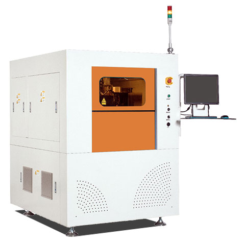
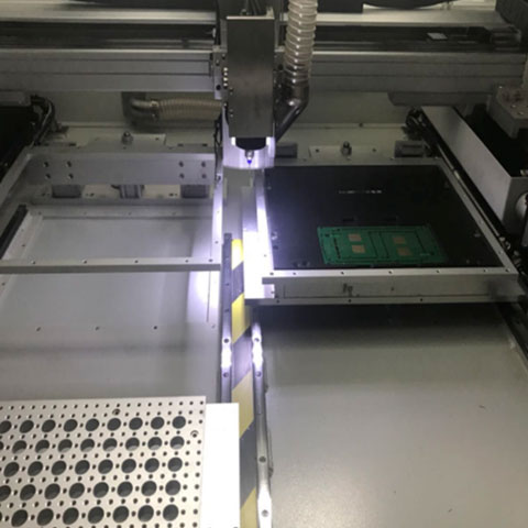
The only mathematical way to guarantee zero delamination is to entirely remove physical force from the equation. This is precisely why leading global EMS providers and Tier-1 automotive suppliers are rapidly upgrading to a laser depaneling machine.
However, we must emphasize an critical point: not all lasers are created equal. If you are processing rigid-flex materials, you must understand the difference between older CO2 lasers and modern UV lasers.
The Problem with CO2 Lasers (Thermal Damage)
A standard CO2 laser operates at a far-infrared wavelength (typically 10.6 µm). It cuts by using raw, intense thermal energy to heat, melt, and eventually vaporize the bulk material. While a CO2 laser is incredibly fast and cost-effective for cutting thick, standard rigid FR-4 boards, it is highly problematic for rigid-flex.
The intense heat from the CO2 beam boils the acrylic adhesive layers and literally melts the polyimide, creating a massive Heat-Affected Zone (HAZ). This excessive thermal stress ironically causes the exact same delamination and carbonization (burned black edges) you are trying to avoid.
The Superiority of 355nm UV Lasers (Cold Ablation)
To successfully and safely process rigid-flex boards, we highly recommend utilizing a Diode-Pumped Solid-State (DPSS) 355nm Ultraviolet (UV) Laser.
UV lasers operate through a completely different physical mechanism known as photochemical “cold ablation.” Instead of burning the material, the extremely short-wavelength, high-energy UV photon directly breaks the molecular bonds of both the FR-4 glass and the polyimide. The material essentially turns to dust and is evacuated instantly by a localized vacuum.
Because the cutting is done so rapidly on a molecular level (in microseconds), the surrounding board material simply does not have time to absorb damaging heat.
The Technical Proof: Advanced UV lasers utilize short-pulse technology to drastically minimize heat transfer. Studies show that the Heat-Affected Zone (HAZ) with these 355nm lasers can be tightly controlled to less than 10 micrometers, compared to the 50-100 micrometers seen with older CO2 lasers. The result is a mathematically perfect, burr-free edge with absolutely zero thermal layer separation.
3. Best Practices: 3 Steps to Optimize Rigid-Flex Laser Singulation
Transitioning to laser technology requires more than simply buying a new piece of equipment and plugging it into your factory floor. To truly maximize your Return on Investment (ROI) and achieve zero-defect manufacturing, you need to rethink your entire production process. Based on our deployment experience across dozens of high-end manufacturing facilities, here are the three best practices you should implement immediately.
Practice 1: Redesign Your Panels to Maximize Material Yield
How to Start: Rigid-flex substrates (especially those using high-grade Kapton and specialized adhesives) are significantly more expensive than standard rigid FR-4. If your engineers are migrating from mechanical routing to laser cutting, they must stop leaving massive 2.0mm to 3.0mm routing channels between your individual boards.
The Solution: A UV laser beam is incredibly precise. When properly focused, the laser beam diameter is a microscopic 20μm to 25μm (0.025mm). This means you can nest your individual PCB outlines practically touching each other on the manufacturing panel.
The Result: By updating CAD layouts to take advantage of the tiny laser kerf, we have seen engineering teams increase the net usable boards on a single panel by up to 30%. When you are dealing with expensive polyimide laminates, recovering 30% of your raw material in every single batch instantly offsets the capital expenditure of the laser machine.
Practice 2: Utilize Dynamic Software Parameter Control
How to Start: A rigid-flex board has variable thicknesses by design. The rigid FR-4 connector sections might be 1.6mm thick, while the dynamic flexible polyimide tail might only be 0.15mm thick. You absolutely cannot use the same laser power and speed for the entire cut path.
The Solution: Modern laser software allows you to program dynamic pulse energy adjustments on the fly. You must set the machine to use high-repetition, higher-energy pulses to efficiently ablate through the thick FR-4 core. However, the exact millisecond the laser crosses over to cut the flexible tail or expose an EMI shield foil, the software must instantly drop the pulse energy and adjust the scanning speed.
The Result: This dynamic “smart pulsing” approach ensures you cleanly slice the delicate flex sections without causing thermal delamination, while maintaining an aggressive cycle time on the thicker rigid sections.
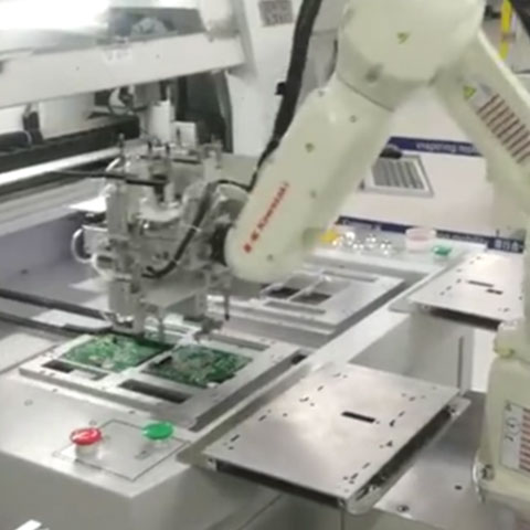
Practice 3: Eliminate Manual Handling with Smart Automation
How to Start: The cleanest, most stress-free laser cut in the world is completely useless if a factory operator accidentally bends or tears the flexible circuit while manually pulling it out of a holding jig.
The Solution: Integrate your laser directly into your factory network utilizing automated handling systems. The equipment should use high-resolution CCD cameras (vision alignment) to automatically compensate for any panel stretch or warpage—which is very common during rigid-flex lamination. After the cut is complete, vacuum-assisted robotic effectors should gently lift the separated rigid-flex circuits and place them directly into ESD-safe packaging. By removing manual human handling, you entirely eliminate operator-induced microcracks.
4. Data Breakdown: Rigid-Flex Singulation Comparison
To help your engineering, quality, and purchasing teams make an informed, data-driven decision, we have compiled a definitive comparison of depaneling methods specifically applied to Rigid-Flex PCB materials.
Keeping mechanical strain and thermal damage as low as possible is the absolute key to preventing delamination.
| Depaneling Technology | Mechanism of Action | Delamination Risk | Heat-Affected Zone (HAZ) | Kerf Width (Space Required) | Recommended For Rigid-Flex? |
| 355nm UV Laser | Non-contact Photochemical Ablation | Zero (Safest) | Extremely Low (<10 µm) | ~20 – 25 µm (Max Yield) | Highly Recommended |
| 10.6µm CO2 Laser | Non-contact Thermal Melting | Moderate to High | High (>50 µm) | ~100 µm | Not Recommended (Melts PI) |
| CNC Router Bit | Physical Milling & Tearing | High (Flute tears flex) | N/A (Mechanical Stress) | 1.5mm – 3.0mm (High Waste) | High Risk (Yield Loss) |
| Die Punching | Physical Impact Shock | Critical (Crushes traces) | N/A (Mechanical Stress) | Variable | Unacceptable |
Conclusion based on industry field data: For processing sensitive flexible and rigid-flex circuits, the 355nm UV laser is the only technology that guarantees zero mechanical stress and zero thermal delamination.
5. Frequently Asked Questions (FAQ)
Q1: Why do my rigid-flex boards peel at the edges immediately after using a mechanical router?
A: This edge peeling is classic delamination caused by mechanical shear stress. The high-speed rotating micro-flutes of the router bit catch the soft, flexible polyimide layer and physically drag it away from the rigid FR-4 core. This brute force destroys the sensitive acrylic adhesive bond between the layers.
Q2: Can we save money by using a standard CO2 laser to cut our rigid-flex PCBs?
A: We strongly advise against it. While CO2 lasers are excellent for standard, thick FR-4 rigid boards, they operate via thermal ablation (intense infrared heat). This heat rapidly melts the delicate polyimide films and boils the internal adhesives, which frequently causes thermal delamination, warping, and carbonization (burning) on the edges. You must use a “cold” 355nm UV laser for flex materials.
Q3: How much space do our PCB designers need to leave between rigid-flex boards for a UV laser cut?
A: A major financial advantage of upgrading to a UV laser is the incredibly small kerf width, which is typically around 20 to 25 micrometers (0.025mm). Unlike a router that needs a 2mm gap, you can nest your board designs virtually touching each other. This drastically reduces substrate waste and saves significant money on expensive rigid-flex laminates.
Q4: Is UV laser cutting actually faster than mechanical routing?
A: In terms of the raw, straight-line feed rate through a thick 1.6mm FR-4 section, a heavy-duty mechanical router might move faster on paper. However, in terms of overall manufacturing throughput (OEE), the laser wins effortlessly. A laser system completely eliminates the need for post-cut edge-cleaning stations, secondary routing passes, router bit tool changes, and costly QA rework due to delamination.
Q5: Does a laser depaneling machine require frequent consumable changes like our mechanical router does?
A: No. This is one of the most critical factors in the ROI calculation for factory owners. Unlike mechanical routers that require you to purchase, track, and replace expensive solid carbide bits every few hundred panels, a laser system has absolutely zero physical cutting consumables. The cut path is defined entirely by software, which drastically lowers your Total Cost of Ownership (TCO) over the lifespan of the machine.