
How the Right Spindle Improves PCB Routing Accuracy and Reduces Tool Wear
Зміст
Engineering position
The spindle is part of the dimensional and quality chain in PCB routing. It locates and drives a small cutting tool at high speed while the machine motion system follows the programmed outline. If spindle runout, clamping, thermal condition, or speed stability moves outside control, the tool no longer follows the intended path in the same way. Edge quality can deteriorate, dimensions can drift, cutting load can rise, and router bits can wear or break earlier.
For a large manufacturer, the correct spindle is not simply the model with the highest advertised speed. It is the spindle that maintains the required process capability across the plant’s materials, route lengths, tool diameters, duty cycle, maintenance plan, and acceptance limits. We specify it as a production subsystem, then prove it with real panels.
Specification rule: Write spindle requirements in terms of measurable machine conditions and board results. A maximum-speed number without runout, thermal, load, interface, service, and qualification requirements is not a complete specification.
Build a spindle-to-board error budget
Routing accuracy does not come from one component. Machine axes, vision alignment, panel support, fixture or gripper repeatability, tool diameter, tool deflection, spindle runout, thermal change, program geometry, and inspection method all contribute. An error budget forces the team to identify those contributors and prevents every dimensional issue from being assigned to the spindle.
| Contributor | Production effect | Control evidence |
|---|---|---|
| Spindle and collet runout | Tool path variation, load, edge inconsistency, wear | Approved measurement method and trend |
| Tool geometry and insertion | Kerf, stiffness, reach, balance, breakage risk | Controlled part number and setup standard |
| Thermal condition | Change after warm-up or long duty cycle | Warm-up rule and sustained-run checks |
| Axis and vision performance | Program-to-panel positioning | Machine calibration and fiducial verification |
| Panel support | Board movement, vibration, local strain | Fixture or gripper qualification |
| Dust extraction | Recutting, heat, contamination, tool load | Source-capture inspection and maintenance |
The spindle must be evaluated inside the pcb router machine, not on a datasheet alone. A precise spindle cannot compensate for panel movement or an incorrect tool. Likewise, a rigid fixture cannot compensate for a damaged collet or uncontrolled runout.
Specify the operating window, not only the maximum
Speed and load capability
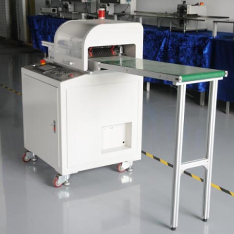
List the tool diameters, materials, panel thicknesses, route lengths, engagement conditions, and expected duty cycle. Then ask the supplier to identify the recommended operating window and monitoring available for those conditions. The process should run with margin rather than at a catalog maximum during every panel.
Spindle speed and feed work together. If feed is too low for the selected speed and tool, the cutter may rub, generate heat, and wear without producing useful material removal. If feed or engagement is too aggressive, load, deflection, edge damage, or breakage can rise. The correct relationship must be developed with the tool supplier, equipment supplier, and production-panel results.
Runout and tool interface
Specify where runout is measured, which test tool or gauge is used, the spindle condition, and the acceptance limit supplied for that system. A value at the spindle nose is not automatically the same as runout at the cutting edge. Collet cleanliness, wear, tightening method, tool insertion depth, and tool shank condition all affect the assembled result.
Haas spindle maintenance guidance, although written for machining centers rather than PCB routers, demonstrates the general engineering discipline: keep the spindle interface clean and measure runout with a defined method. For your depaneling equipment, use only the procedure and limits approved by its manufacturer.
Thermal behavior and duty cycle
A spindle may perform differently at startup, after warm-up, and during continuous production. Define the warm-up requirement, cooling or air supply, ambient limits, duty pattern, and checks after a sustained run. If the plant operates multiple shifts, the acceptance test should reproduce that operating pattern instead of testing only a cold machine.
Qualify the spindle with a controlled test protocol
Use the protocol to separate spindle capability from tool, panel, support, and programming effects. Freeze the panel lot, tool part number, insertion method, fixture or gripper, extraction configuration, route program, inspection method, and machine condition. Change one major factor at a time when comparing spindle or parameter options.
- Inspect the spindle, collet, tool holder interface, air or cooling supply, and maintenance status before the test.
- Measure the supplier-defined runout condition and record the method, instrument, location, and machine temperature.
- Run the approved warm-up and verify stable operating conditions before dimensional comparison.
- Process representative panels across enough route length to expose heat, wear, vibration, and dust effects.
- Record edge condition, dimensions, tool usage, spindle load or alarms, noise changes, dust behavior, and operator interventions.
- Inspect samples from multiple points in the run and compare them with the same measurement system.
- Repeat critical checks after tool change, planned stop, and controlled restart.
A standalone bottom-cut pcb router can support controlled offline process development, while an in-line automatic pcb separator adds transfer and line-interaction variables. The acceptance protocol should match the final architecture. Do not transfer a spindle conclusion from an open bench trial to an automated cell without checking the integrated conditions.
Connect spindle choice to tool life
Router-bit life should be measured against accepted route length or accepted boards, not simply the number of tools purchased. A tool can still rotate after edge quality or dimensions leave the approved window. Define the wear limit from product evidence and replace the tool before the process loses capability.
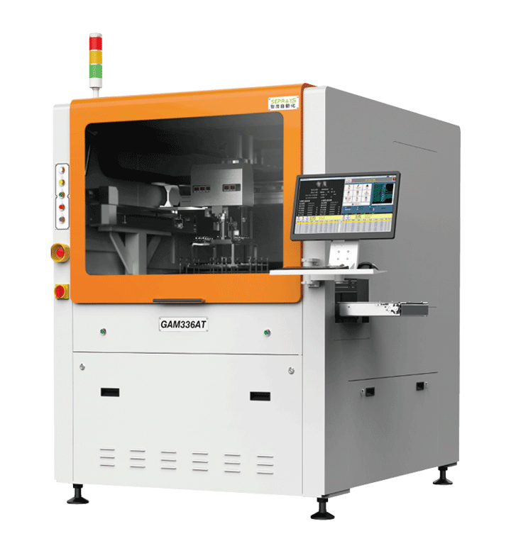
When tool life falls, follow a disciplined sequence. Confirm the exact tool and material. Inspect insertion depth, collet condition, and runout. Check spindle warm-up, speed, load, air or cooling, and alarms. Verify panel support and route engagement. Inspect source capture, hose condition, filters, and debris near the cut. Compare the program and parameters with the released baseline. This sequence avoids changing speed or feed before the physical system is understood.
Review suitable pcb depaneling accessories together with the spindle. Collets, router bits, dust brushes, extraction components, fixtures, and detection options affect the same cutting system. Procurement should control compatible part numbers and revisions instead of allowing visually similar substitutes into production.
Define maintenance around measurable condition
A spindle maintenance plan should state the task, interval or trigger, responsible role, approved method, acceptance limit, required tools, and record. “Check spindle” is not a usable instruction. “Measure the approved runout condition after the defined warm-up using the specified test tool and escalate above the supplier limit” creates a repeatable control.
| Maintenance element | Routine control | Escalation evidence |
|---|---|---|
| Tool and collet interface | Cleanliness, wear, insertion, approved tightening | Damage, slip, repeat runout, abnormal marks |
| Spindle condition | Warm-up, sound, temperature, load, alarms | Trend change or supplier limit exceeded |
| Air or cooling | Pressure, flow, temperature, leaks, service items | Out-of-range supply or repeated overheating |
| Dust capture | Brush or hood, hose, filter, seals, collector | Visible escape, loading, blockage, damaged component |
| Machine geometry | Supplier calibration and vision checks | Dimensional trend not explained by product or tool |
Trend measurements when practical. A single pass/fail reading protects today’s lot, while a trend can reveal gradual wear and help maintenance plan the intervention. Keep the post-maintenance first-piece result with the machine record so the factory can show that equipment condition and product release were connected.
Use a procurement and acceptance specification
- Approved PCB materials, thickness range, tool sizes, route geometry, and expected production duty.
- Spindle speed operating range, control interface, load or condition monitoring, and alarm behavior.
- Runout definition, measurement location, method, supplied test equipment, and acceptance limits.
- Warm-up, air, cooling, ambient, extraction, maintenance, and installation requirements.
- Collet and tool compatibility, controlled spare parts, expected wear items, and replacement procedure.
- Production-panel test covering cold start, warm state, sustained run, tool change, stop, and restart.
- Training, technical documentation, remote diagnostics, field service, repair path, and backup strategy.
Compare spindle capability across the relevant pcb depaneling machine portfolio only after the plant defines the product and duty profile. The appropriate configuration for a high-mix engineering area may differ from the one required for continuous in-line production.
Final selection logic
Select the spindle and machine combination that demonstrates the required board capability with controlled tool consumption and a maintainable operating window. Give preference to evidence from representative panels, sustained running, documented measurement methods, accessible maintenance, controlled spares, and a supplier response model that matches the plant’s uptime requirement.
The best result is not the smallest runout claim or the highest speed in isolation. It is a stable routing process that production can run, quality can verify, maintenance can restore, and engineering can transfer across shifts without losing control.
FAQ
Which spindle characteristics matter most for PCB routing accuracy?
Runout at the tool, speed stability, bearing condition, thermal behavior, collet condition, tool clamping, available torque, and integration with the machine motion and dust-control system all matter.
Can a higher spindle speed automatically improve edge quality?
No. Speed must work with tool geometry, feed, material, engagement, support, and extraction. Excessive speed can increase heat or wear without improving the accepted result.
How should a factory set a spindle acceptance limit?
Use the machine and spindle supplier’s approved measurement method and limits, then link them to board-level capability through a production-panel qualification.
What usually causes premature router-bit wear?
Common contributors include excessive runout, poor collet condition, unsuitable speed or feed, excessive engagement, weak board support, recutting debris, heat, and using the wrong tool for the material.