![]()
Automatic Depaneling Equipment for 24/7 Production: Stability and Reliability Benefits
To successfully run automatic depaneling equipment 24/7, it must be designed as a maintainable process, not just a fast machine. Reliable round-the-clock output depends on stable material transfer, controlled tools, dust extraction, recipe management, alarm recovery, preventive maintenance, spare parts, and enough buffer capacity to absorb short stops.
Night shifts reveal weaknesses that day-shift support can hide. A sensor that needs frequent cleaning, a tool changed by feel, or an alarm that only one engineer understands can halt production for hours. The goal for 24/7 operation is graceful recovery: operators should easily recognize faults, protect the boards, and restore the process using clear standard operating procedures (SOPs).
目次
Why Depaneling Matters After SMT
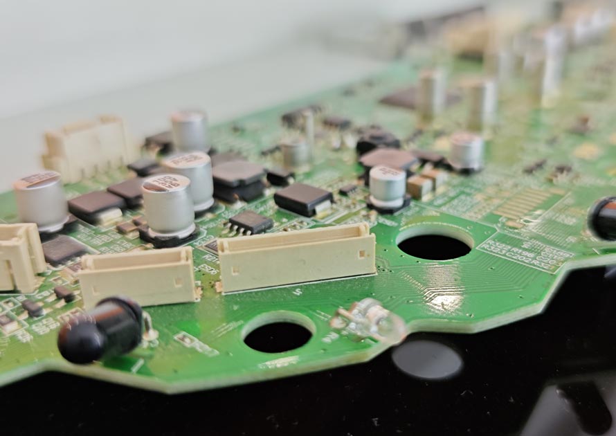
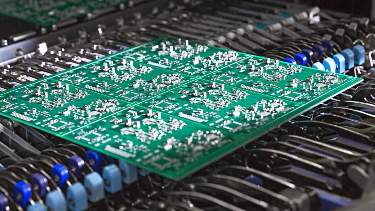
Depaneling sits near the absolute end of the assembly process. By this point, the factory has already paid for the bare PCB, components, solder paste, placement, reflow, inspection, testing, and handling. Therefore, a separation defect destroys significantly more value than a raw-board defect.
A 2024 peer-reviewed study on PCB panel depanelization emphasizes the need to consider diagnostics and process effects during panel manufacture. This supports a practical rule for implementation: choose and validate depaneling as an engineering process, not just a simple final cut. Automation cannot correct poor panel design, an unsupported board, or the wrong cutting technology. Those baseline engineering choices still determine yield.
How Automation Transforms the Process
When implemented correctly, automation removes avoidable variation and provides the following benefits:
- Stable shift-to-shift output: Programs and automated handling repeat the exact same process around the clock.
- Earlier wear detection: Tool and process checks catch drift before it becomes a mass scrap event.
- Faster recovery: Clear alarms and standardized recovery steps shorten minor stops.
- Planned maintenance: Service work transitions into scheduled windows rather than emergency downtime.
- Consistent traceability: Machine and barcode records support root-cause investigations across all shifts.
Phase 1: Start with Real Factory Data
Before approving a machine for 24/7 use, run an extended acceptance test with normal materials, product changes, tool changes, and planned operator breaks. A short showroom demo cannot prove round-the-clock reliability.
Collect the Product Data:
- Panel dimensions, thickness, material, weight, and warpage.
- Gerber or CAD data and the current panel revision.
- Board outline, routing tabs, v-score lines, and required edge quality.
- Component height and clearance from sensitive parts to the cut path.
- Current output, changeover time, scrap causes, and shift patterns.
- Loading, unloading, tray, conveyor, barcode, and MES requirements.
Map the Full Cycle:
Follow one panel from the upstream conveyor to the next accepted process. Count every touch, wait, scan, fixture action, cut, inspection, and transfer. This exposes the real constraint and prevents a common mistake: buying a faster cutter while leaving a slow manual sorting process untouched.
Phase 2: Choose the Right Technology and Architecture
Do not force every SKU through one method simply because the machine is already on the factory floor. Successful plants often use a mixed strategy. The purpose of standardization is to make each approved route repeatable, not to pretend every board carries the same risk.
Match the Cutting Technology to the Product
| Process | Best Fit For | Main Control Points |
| Routing | Rigid PCBAs, complex contours, high product mix, tabs, mouse bites. | Fixture/gripper support, bit wear, spindle parameters, dust extraction. |
| レーザ | FPC, rigid-flex, thin materials, dense components, low-stress needs. | Material absorption, heat-affected zone (HAZ), fumes, optical maintenance. |
| V-Groove | Straight pre-scored rigid panels, long strips, repeat high-volume products. | Score quality, remaining web, board support, blade condition, component clearance. |
| Punching | Stable high-volume designs where a dedicated die is justified. | Die condition, mechanical stress, loading safety, tooling storage. |
Select the Right Architecture for Your Production Line
Based on real-world ROI and yield requirements, matching the architecture to your product is critical:
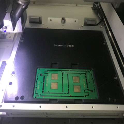
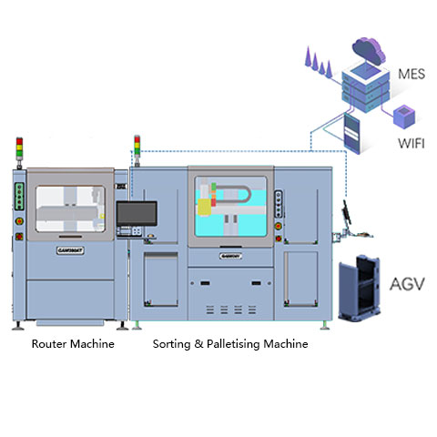
- For Complex Rigid Boards (FR-4): An inline PCB Router machine is the strongest choice for high-mix, complex contours. Advanced platforms from SEPRAYS offer track loading, vision teaching, programmable cutting, automatic tool changes, and conveyor unloading. Add a downstream buffer to prevent brief downstream stops from forcing a router shutdown.
- For FPC and Highly Sensitive Components: When “Zero Stress” is non-negotiable (such as in automotive electronics or mobile devices), a Laser depaneling machine guarantees no mechanical contact, eliminating component micro-cracks and ensuring micrometer-level precision.
- For High-Volume Straight Cuts: If you are processing straight, pre-scored panels where speed and lowest cost-per-board are the priorities, an automatic V-Groove Saw depaneling system delivers the fastest cycle times.
- For Ultra-High Volume & Stable Designs: When a dedicated die is economically justified, a punching machine provides instantaneous separation with high repeatability, ideal for specific OEM brand manufacturers.
Phase 3: A Practical Implementation Sequence
To ensure a smooth rollout and achieve true inline depaneling automation, follow these steps and mitigate risks before release:
- Baseline the process: Agree on the specific problem automation will solve (e.g., high labor costs vs. edge burrs).
- Review DFM risks: Analyze the separation path for vulnerabilities.
- Define line interfaces: Establish conveyor heights, travel directions, signals (SMEMA/Hermes), buffers, and unloading mechanisms.
- Run samples: Approve edge quality, dimensions, component safety, dust control, and cycle times using real panels.
- Create SOPs: Release cutting recipes and define strict first-piece inspection rules.
- Train operators: Cover normal work, tool changes, cleaning, alarms, and escalation procedures.
- Conduct an Acceptance Test: Ensure the test includes normal operators, tool replacements, and alarm recovery—proving the process you will actually run.
Key Risks to Control:
- Wrong product/program selection.
- Worn router bits, blades, filters, or transfer parts.
- Insufficient support near the cut path.
- Dust or debris reaching the PCBA or vision system.
- Unclear inspection criteria or maintenance tasks that shifts cannot complete.
Phase 4: Post-Launch KPIs and Maintenance
A new machine can look busy without actually improving the factory. Track these operational measures weekly during ramp-up, then transition to monthly reporting:
- Accepted boards per scheduled hour: Count good output after inspection, not just machine cycles.
- First-pass yield: Separate cutting defects, handling defects, and upstream defects.
- Interventions per shift: Record why an operator opened the cell, cleared an alarm, or changed a tool.
- Changeover time: Measure from the final good board of one job to the first approved board of the next.
- Tool and consumable use: Correlate router bits, blades, filters, and nozzles to actual production volume.
Maintenance and Change Control
Automatic equipment requires disciplined maintenance. A small problem will be repeated rapidly by an automated machine.
Software control: Manage recipes as carefully as mechanical parts. Keep approved files, revision histories, and rollback methods. If a cut path or speed changes, re-run first-piece checks.
Daily tasks: Clean the vision area, check extraction, inspect contact surfaces, and review alarms.
Tool changes: Record why a tool was changed, its completed route length, the material cut, and edge condition. This builds a data-driven replacement rule rather than relying on guesswork.
FAQ
What makes a depaneling machine suitable for 24/7 use?
Look for robust motion control, tool monitoring, accessible maintenance, reliable extraction, clear alarms, recipe control, spare-part support, and proven extended-run performance.
How much buffer is needed?
Size buffers from the normal cycle time, expected recovery time, upstream behavior, and downstream capacity. There is no universal board count.
Which spare parts should be kept on site?
Base the list on the supplier’s critical-parts analysis. Router bits, filters, sensors, belts, nozzles, and wear items are common, while some sites also stock higher-value modules.
How should night-shift teams be trained?
Train routine operation, first-piece checks, tool changes, cleaning, safe alarm recovery, escalation rules, and how to protect work-in-process during a stop.