![]()
How to Choose the Right PCB Depaneling Machine for Your Production Requirements
If you are a process engineer or an SMT production manager, you already know the pain of watching a perfectly assembled, high-value circuit board get destroyed at the very last step of manufacturing. You’ve invested massive capital into your pick-and-place systems, but if your board singulation process is flawed, you are quite literally throwing money away.
Here is the direct answer you are looking for: Choosing the right equipment comes down entirely to your board’s material, component density, and production volume.
- If you are processing high-density interconnect (HDI) boards, rigid-flex materials, or automotive boards with components extremely close to the edge, you must upgrade to a pcb laser cutting machine.
- If you are running complex geometric FR-4 panels and have a bit more clearance, a standard pcb router machine is your reliable workhorse.
- If you only cut massive volumes of straight V-scored boards (like LED lighting strips), a v-groove cutting system is the fastest.
- If you are making simple, low-cost consumer electronics in extreme volumes, a punching machine will give you instant throughput.
Why does getting this right matter so much? Because selecting the correct physical cutting mechanism directly eliminates mechanical stress, prevents invisible microcracks in sensitive components like MLCCs, maximizes your material yield, and determines your overall Return on Investment (ROI). In this guide, we are sharing our direct, hands-on factory experience to help you make the smartest equipment choice for your production floor.
1. The Hidden Cost of Choosing the Wrong Depaneling Technology
When our team walks onto a factory floor to audit an EMS (Electronic Manufacturing Services) provider, the most common—and expensive—mistake we see is engineers trying to use one outdated piece of equipment for every single product SKU.
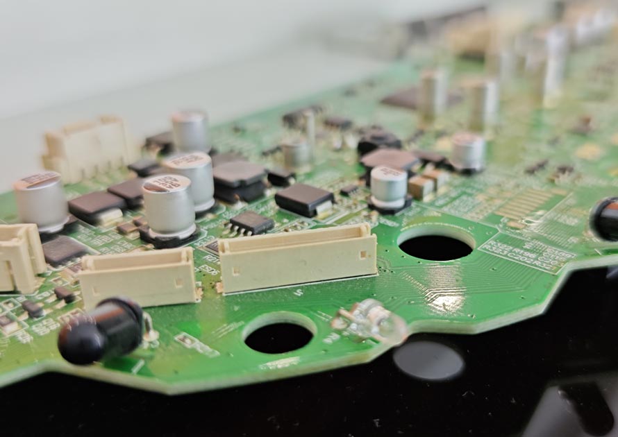
Here is the reality of modern electronics: PCB designs are shrinking. Components are being placed closer and closer to the board’s edge. When you use traditional, aggressive mechanical separation methods (like snapping by hand or using dull saw blades), you force severe bending strain through the fiberglass substrate.
This vibration doesn’t just vanish; it transfers directly into your rigid solder joints, causing microscopic fractures in ceramic capacitors and BGA components. These microcracks are a factory owner’s worst nightmare because they often pass your end-of-line electrical testing. The device ships to the customer, and months later, normal thermal cycling or minor vibration causes the crack to expand into a dead short. Choosing the wrong machine doesn’t just cost you the price of the equipment; it costs you scrapped boards, wasted components, and potentially your reputation with high-value OEM clients.
2. Comparing the Core Depaneling Technologies
To make a data-driven decision, you need to understand the physical mechanics behind the primary separation methods available on the market today. Let’s break them down based on our field experience.
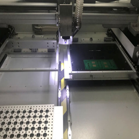
The PCB Router (The Flexible Workhorse)
A pcb router machine uses a high-speed CNC spindle—typically spinning between 40,000 and 60,000 RPM—equipped with a solid carbide micro-milling bit to cut through the connecting tabs (often called mouse bites) of a panelized board.
- The Good: It is the industry’s go-to choice for complex board shapes, curved edges, and internal cutouts. Among all contact-based mechanical methods, the router generates the lowest mechanical stress. It is highly programmable via CAD/Gerber data, meaning you don’t need to buy custom physical dies for every new board.
- The Bad: It produces abrasive fiberglass dust, which means you need a robust industrial vacuum extraction system. It also relies on consumable router bits that wear out, lose their diameter, and need frequent replacement.
- When to Use It: This is ideal for automotive ECUs, industrial controls, and any high-mix production facility running standard rigid FR-4 materials.
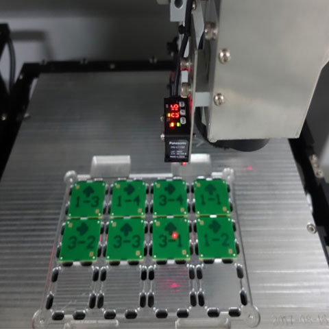
💡 Best Practice 1: Evaluate Component Density First (The DFM Check)How to start: Before you even look at machine specs, look at your Gerber data. Measure the exact distance between your closest sensitive components (like ceramic capacitors) and the intended cut line.The solution: If your components are closer than 1.0mm to the edge, mechanical saws or punches will almost certainly fracture them. You are instantly forced into choosing routing or laser. Furthermore, if you are processing delicate polyimide flexible circuits (FPC), mechanical routers will physically tear the material. In these cases, you absolutely must select a UV laser system to prevent thermal damage and layer delamination.
The Laser Depaneling Machine (The Zero-Stress Future)
A laser depaneling machine represents the absolute cutting edge of PCB separation. Instead of using a physical carbide blade or bit, it utilizes a highly focused beam of light (usually a 355nm UV laser) to vaporize the material layer by layer. In the engineering world, we call this “cold ablation.”
- The Good: It is a 100% non-contact process. That means absolutely zero mechanical stress, zero vibration, and zero fiberglass dust. It offers mind-blowing precision, with cutting tolerances as tight as ±20 microns. This allows your design engineers to place components practically touching the cut line, saving massive amounts of board space.
- The Bad: The initial capital expenditure (CapEx) is definitely higher than standard mechanical systems. Also, if you are cutting extremely thick (>1.6mm) FR-4 boards, the raw cutting speed can be slower than a heavy-duty physical router.
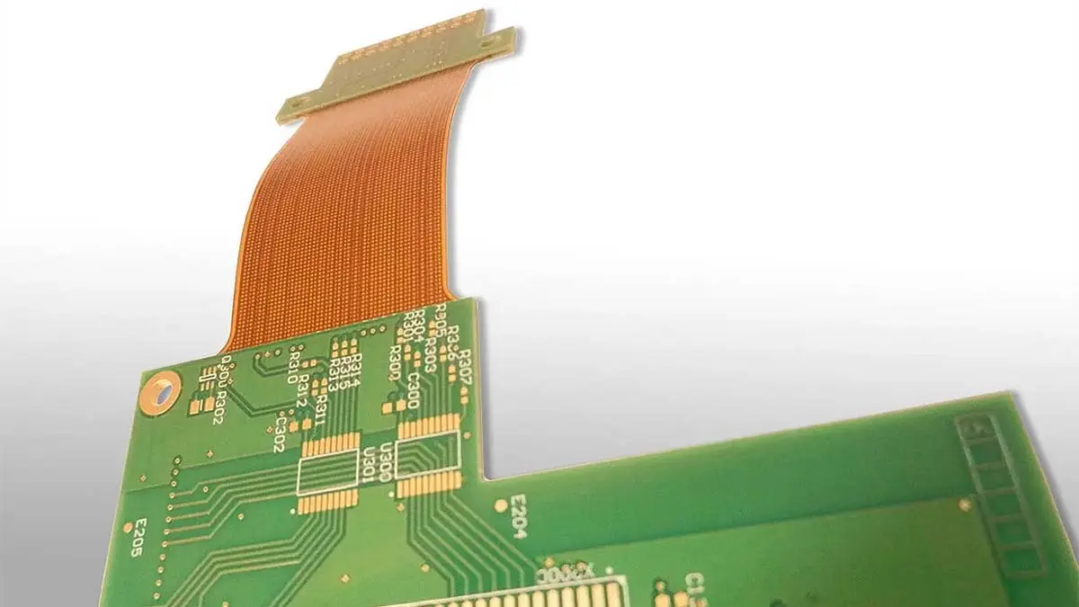
- When to Use It: A laser is mandatory for rigid-flex boards, ultra-thin wearable medical devices, 5G communication boards, and strict automotive applications where zero-defect technical cleanliness is a hard requirement.
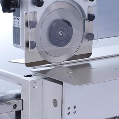
The V-Groove Saw (The High-Speed Slicer)
A v-groove saw depaneling system uses a motorized, rotating diamond or carbide circular blade to slice directly through pre-scored V-cut lines on the PCB panel.
- The Good: It is incredibly fast and highly efficient for mass production. It easily handles thick, dense boards, including the aluminum-backed metal core PCBs (MCPCBs) that are extremely common in the LED lighting industry.
- The Bad: It is strictly limited to straight-line separations. You cannot cut curves. The wedging action of the circular blade generates moderate mechanical stress perpendicular to the cut, so you must keep components at a safe distance from the edge.
- When to Use It: Best for high-volume manufacturing of identical, rectangular boards (like memory modules or LED arrays).
💡 Best Practice 2: Calculate the True Total Cost of Ownership (TCO)How to start: We always tell our clients to stop looking exclusively at the upfront price tag of the machine. You must calculate the operational running cost over a three-to-five-year period.The solution: While a CNC router is significantly cheaper to purchase than a high-end UV laser, you must factor in the hidden costs. How much are you spending on solid carbide router bits every week? What is the labor cost for operators to stop the machine and change those bits? How much do specialized holding jigs cost for every new product? Because a pcb laser cutting machine operates purely via software and light, it has virtually zero physical consumables. For high-volume contract manufacturers, the higher initial cost of a laser system actually offers a faster ROI because it entirely eliminates tooling waste and manual rework.
The Punching Machine (The Instant Stamper)
A punching machine uses a custom-machined steel die to stamp out individual PCBs from the panel in a single, powerful press stroke.
- The Good: It offers the highest possible raw throughput. An entire multi-board panel can be separated in two seconds flat. It is highly cost-effective for massive, unchanging production runs.
- The Bad: The violent impact shock creates severe mechanical stress, which is highly dangerous for modern surface-mount components. Additionally, every time your engineers update a board design, you must buy and wait weeks for a brand-new custom-machined die.
- When to Use It: Ideal for simple, low-cost consumer electronics, toys, and basic home appliances where precision and mechanical stress are simply not critical factors.
3. The Data-Driven Shift to Laser and Automation
To give you a broader perspective on how the market is moving, we continuously track factory adoption rates globally. The data is crystal clear: the entire electronics manufacturing industry is transitioning rapidly away from brute-force mechanics and moving toward precision and smart automation.
- Automation Growth: According to recent global market analyses, approximately 68% of Tier-1 EMS providers now utilize fully integrated, automated depaneling solutions, stepping completely away from offline, manual-feed machines.
- The Rise of Laser Technology: Recent market data shows an astonishing shift: over 62% of new PCB assembly lines installed globally in 2024 prioritized laser systems over mechanical ones. This is being driven heavily by the explosion in electric vehicle (EV) electronics, 5G infrastructure, and HDI consumer devices where failure is not an option.
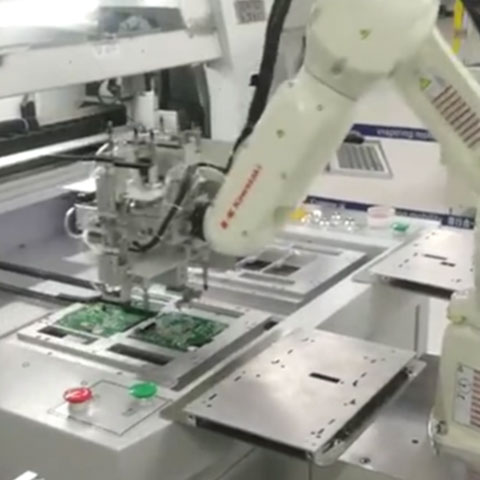
💡 Best Practice 3: Plan for Future Automation IntegrationHow to start: Determine if your factory management is moving towards Industry 4.0 and full SMT line automation. Buying a standalone, offline machine might save money today, but it creates a bottleneck tomorrow.The solution: If your long-term goal is to eliminate manual operator handling (which introduces human error, dropping risks, and static discharge), you need to choose equipment capable of inline depaneling. Look for machines equipped with standard SMEMA or IPC-CFX connectivity, automated CCD vision alignment systems, and robotic arm integration that can gently unload separated boards directly into ESD-safe blister trays.
4. Quick Reference Selection Matrix
We use this exact matrix when consulting with factory owners. Use it to quickly align your production priorities with the right equipment.
| Production Requirement | Your Highest Priority | Recommended Machine Choice | Expected Edge Quality |
| High Mix / Complex Shapes | Flexibility & Low Tooling Cost | CNC Router | Smooth (Requires strong vacuum) |
| Rigid-Flex / High-Density | Zero Stress & High Precision | UV Laser | Burr-free, immaculate |
| Straight V-Cuts / MCPCB | Raw Speed & Thick Materials | V-Groove Saw | Good (Moderate dust) |
| Extreme Volume / Simple | Maximum Throughput Speed | Die Punching | Fair (High physical stress) |
5. Frequently Asked Questions (FAQ)
Q1: We process a mix of standard rigid FR-4 boards and flexible circuits. Can one machine handle both?
A: If you absolutely must use one single machine for both materials, a UV laser is the only viable option. Mechanical routers are excellent for rigid FR-4 but will catch, tear, and destroy the delicate polyimide layers of a flexible circuit. A UV laser safely cuts both materials using cold ablation.
Q2: Are PCB laser machines slower than traditional mechanical routers?
A: If you are strictly looking at the raw feed rate through very thick (>1.6mm) FR-4 panels, a heavy-duty mechanical router might be faster. However, lasers require zero tool-change downtime, no edge-cleaning stations, and generate zero rework scrap. When you measure Overall Equipment Effectiveness (OEE) across a full shift, laser throughput is actually highly competitive.
Q3: What is the main disadvantage of using a die-punching machine for our SMT line?
A: The two main disadvantages are mechanical shock and tooling lead time. The violent physical impact can instantly fracture sensitive MLCCs. Additionally, every time your engineering team updates a board layout—even slightly—you must wait weeks to have a new custom steel die machined, completely killing your factory’s agility.
Q4: How do we properly control the dust when using a mechanical PCB Router?
A: Proper CNC routing requires an integrated, high-CFM industrial vacuum system. The vacuum nozzle must be located directly at the spindle head to evacuate the abrasive fiberglass chips the exact millisecond they are generated. Ensuring your cutting parameters (balancing RPM vs. Feed Rate) are optimized also significantly reduces fine dust generation.
Q5: Can we just use a cheaper CO2 laser instead of a UV laser to save money?
A: We strongly advise against this for high-density or flexible boards. CO2 lasers operate via intense thermal melting (infrared heat), which creates a very large Heat-Affected Zone (HAZ). This excessive heat frequently burns the board edges and melts the internal adhesives in rigid-flex boards. UV lasers use short-wavelength photochemical ablation to cut “cold,” preventing thermal damage entirely.