![]()

How to Extend Tool Life in PCB Router Machines for High-Volume Manufacturing
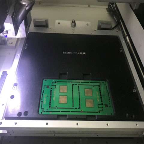
If you are running an SMT production line, we don’t need to tell you that PCB singulation is the most critical final step. All the value has already been added to the board. If a dull router bit cracks a component, leaves a messy burr, or forces an unscheduled machine stoppage, you are bleeding money.
The short answer: To drastically extend the tool life of your PCB router machine, you need to execute three core strategies: balance your spindle RPM with an aggressive feed rate (typically 50–100 mm/s at 40,000–60,000 RPM), utilize multi-level Z-axis depth compensation, and upgrade to TiAlN or DLC-coated solid carbide bits.
Why choose this approach? Because minimizing tool wear isn’t just about saving $15 on a consumable bit. The real benefit is maximizing equipment uptime, securing a zero-defect yield rate, and achieving a highly stable, automated process. In this guide, we are sharing our direct engineering experience from the factory floor to show you exactly how to start, how to solve premature wear, and the data to back it up.
Jadual Kandungan
1. The Hidden Costs of Premature Tool Wear (Why You Must Fix This)
Most factory owners underestimate the financial impact of router bit wear. We often see operators running tools until they literally snap. This is a massive mistake.
When a standard routing tool wears down, it doesn’t just stop cutting—it physically shrinks. A cheap router bit can lose up to 0.15mm in diameter from the time it is new to the time it fails. What does that mean for your production? It means the first board you process will be 0.15mm smaller at the routing tabs than the board cut right before the bit dies. Your finished product panel suddenly grows by 0.3mm across its X and Y locations, completely ruining your mechanical assembly tolerances.
Furthermore, a dull bit stops slicing through the fiberglass and begins rubbing against it. This generates extreme friction and heat, which melts the FR4 epoxy resin right onto the tool. The resulting mechanical vibration transfers stress directly into the PCB, frequently causing micro-cracks in sensitive BGA solder joints.
2. Best Practices: How to Double Your Tool Lifespan
Based on our extensive field experience optimizing inline depaneling systems for EMS providers, here are the actionable steps you can implement today.
Best Practice 1: Master the Spindle Speed vs. Feed Rate Ratio
How to start: Stop assuming that faster spindle speeds are always better. Every cutting operation requires a delicate balance between the spindle speed (RPM) and the feed rate (how fast the tool moves through the material).
How to solve: If you push the tool through the material too quickly, the physical stress will snap the bit. However, the most common mistake we see is the opposite: operators run the spindle extremely fast but move the feed rate too slowly. When this happens, the tool rubs instead of cuts, generating massive heat that destroys the carbide edge.
For standard FR-4 materials, the “sweet spot” in a high-volume production environment is generally a feed rate of 50 to 100 mm/s paired with a spindle speed of 40,000 to 60,000 RPM. Proper speeds ensure the heat transfers into the dust chips rather than soaking into the tool core.
Best Practice 2: Enable Multi-Level Z-Axis Tool Compensation
Why choose this: This is the easiest, most cost-effective way to multiply your tool life immediately. Standard FR4 boards are usually 1.6mm thick. A typical router bit has a cutting flute length of 5mm to 8mm. If you only cut at a single depth, you are destroying a 1.6mm section of the tool while the rest of the cutting edge remains brand new.
How to solve: You must use Z-axis tool compensation in your machine’s software. By automatically shifting the Z-axis up and down the thickness of the PCB, every successive panel is cut on a different, fresh section of the tool. Advanced machines today feature automatic router bit depth adjustment systems that can shift through up to five different depth levels, drastically reducing your bit replacement frequency. This results in exponentially longer tool life and better dimensional stability across your entire batch.
Best Practice 3: Upgrade to Advanced Coatings (TiAlN and DLC)
Why choose this: Standard tungsten carbide is the workhorse of the industry, but high-density FR4 fiberglass is incredibly abrasive. If you are processing large volumes, bare carbide wears out too quickly.
The Data: You are not alone in this shift. In 2024, over 63% of PCB cutting tools sold globally featured advanced coatings like Titanium Aluminum Nitride (TiAlN) or Diamond-Like Carbon (DLC) to extend tool life.
How to solve:
- TiAlN Coatings: This coating can tolerate extreme temperatures (up to ~800°C). At high speeds, it forms a protective aluminum oxide layer that acts as a thermal shield, extending the tool’s life significantly. Studies have shown that when using TiAlN-coated carbide tools, optimizing the feed rate is the primary factor in achieving maximum operational lifespans.
- DLC Coatings: Diamond-Like Carbon provides an extremely low friction coefficient (~0.1 to 0.15). This prevents sticky epoxy resin and copper chips from adhering to the bit, ensuring your cuts remain clean and burr-free for thousands of cycles. Under optimal conditions, a high-quality coated carbide bit can last for 5,000 to 10,000 cuts on standard FR4.
3. Maintenance: The Role of Dust Extraction and Collets
Even with the best parameters and diamond-coated bits, your tool will die prematurely if your machine maintenance is poor.
When fine PCB dust builds up inside the cut channel due to weak vacuum extraction, the router bit is forced to re-cut the abrasive dust chips. This causes “chip packing,” which increases cutting resistance and shatters the tool. Always ensure your vacuum fixtures are operating at maximum capacity.
Additionally, monitor your spindle collets. A worn collet introduces runout (wobble). If your bit is vibrating at 60,000 RPM, the mechanical fatigue will destroy the tool’s cutting edge in minutes, regardless of the coating you use.
4. When Router Bits Aren’t Enough: Exploring Alternative Solutions
Here is the truth: no matter how perfectly you optimize your routing parameters, physical milling will always have limitations. If your OEM clients are demanding zero-stress technical cleanliness, or if you are processing highly sensitive components, it might be time to eliminate the consumable tool altogether.
The Ultimate Upgrade: If you are dealing with ultra-thin rigid-flex boards, densely populated PCBA, or components highly sensitive to vibration, you need a pcb laser cutting machine. A UV laser operates via a “cold” ablation process, vaporizing the FR4 and copper layer by layer. Because there is zero physical contact, there is absolutely no tool wear, no dust, and zero mechanical stress on the board.
High-Volume Straight Cuts: Alternatively, if your panels are strictly straight-line designs, routing them wastes time and tooling. A high-speed v-groove saw depaneling system will process these boards in a fraction of the time without wearing down expensive milling bits.
For Massive Flex Batches: For high-volume, simple shapes (like mass-producing FPC), relying on a punching machine utilizing a custom-designed stamping die is by far the fastest and most cost-effective method.
Quick Reference: Recommended Machining Parameters
To help you get started, we have compiled a baseline data reference for processing standard FR4 substrates. Always start conservative and adjust based on real-time spindle load feedback.
| Material Type | Spindle Speed (RPM) | Feed Rate | Z-Axis Strategy | Best Tool Coating | Expected Tool Life |
| Standard FR-4 (1.6mm) | 40,000 – 60,000 | 50 – 100 mm/s | 3 to 5 levels | DLC / Diamond-Cut | 5,000 – 10,000 cuts |
| Aluminum-Core (IMS) | 30,000 – 45,000 | 20 – 40 mm/s | Single pass / 2 levels | TiAlN / 2-Flute | 1,000 – 2,500 cuts |
| Flexible PCB (FPC) | N/A (High Tear Risk) | N/A | N/A | Use Laser / Punching | N/A |
Frequently Asked Questions (FAQ)
Q1: How long should a router bit typically last before it goes dull?
A: It heavily depends on the material and programming. However, a high-quality solid carbide bit, when properly optimized, should last for 5,000 to 10,000 cuts on standard FR4 boards.
Q2: Why is my router bit leaving white fuzzy burrs on the edges of the PCB?
A: This means the tool is rubbing rather than cutting. It is usually caused by either a heavily worn bit, a spindle speed that is too high, or a feed rate that is too slow. The friction melts the resin instead of shearing the glass fibers.
Q3: Is it better to run the spindle at maximum RPM for a smoother cut?
A: No. While a higher RPM can technically leave a smoother finish, if you do not increase the feed rate to match it, you will burn the tool. Finding the optimal cutting speed for the specific operation is crucial.
Q4: Can we use a standard router machine for depaneling FPC (Flexible Printed Circuits)?
A: It is generally not recommended. Flexible materials are easily deflected by a physical cutter, leading to severe vibration, edge tearing, and poor tolerances. For FPC, we highly recommend switching to a laser depaneling machine.
Q5: What exactly does “Z-axis compensation” mean in PCB routing?
A: Z-axis compensation allows the machine spindle to shift up and down automatically during a production run. Instead of wearing out one specific 1.6mm spot on the router bit, it distributes the cutting wear across the entire length of the flute, drastically extending tool life.